An industrial battery sample is useful only when it is tested as part of the equipment it will power. A label match and a successful first start do not establish that the pack, charger, controller, mechanical enclosure and operating duty cycle will remain compatible through normal work, peak loads, faults and maintenance. Before committing to a volume order, a buyer should agree on a written acceptance plan, collect a baseline configuration, run repeatable bench and equipment tests, record failures, and close every change through a controlled revision.
This guide is a general engineering and procurement framework for OEMs, system integrators and industrial equipment buyers. It is not a substitute for the approved product specification, a qualified safety assessment or the applicable standards for a particular machine and destination market. Numerical limits and pass criteria must come from the exact pack, host equipment and project agreement. YZL POWER supports project review, BMS integration, sampling and production for application-driven battery packs; the final configuration and documents should be confirmed by model.
Define the decision the pilot must support
The purpose of a pilot is not merely to show that a prototype can turn on. It should answer whether a specific, frozen battery configuration can meet a specific equipment requirement with a defined margin and a reproducible manufacturing process. A useful pilot decision has three possible outcomes: release to the next controlled stage, release with documented restrictions and corrective actions, or reject and redesign. Write those outcomes before testing begins. Otherwise, teams tend to reinterpret a test after seeing the result.
Begin with the application rather than an attractive catalog specification. Identify the equipment model and firmware; the electrical bus and charger; continuous, intermittent and regenerative loads; start-up and stall behavior; expected operating hours; installation space; ambient conditions; operator behavior; and service access. Record what happens when the equipment is idle, charging, in transit, stored and near end of discharge. If several machine variants share one battery, list the differences explicitly. A sample that passes on the lightest machine is not automatically approved for every variant.
A pilot matrix should connect every requirement to a method of proof. For example, a peak-current requirement may need a current trace at the actual machine, not only a laboratory power supply. A communications requirement needs message-level evidence with the specified host firmware. A mechanical fit requirement needs a controlled drawing and an installation trial. A document requirement needs the exact model and manufacturer on the report. Assign an owner, acceptance criterion and evidence file to every line.
The minimum pilot packet
Ask the supplier and equipment team to agree on one packet before the sample is built. It should contain a revision-controlled pack drawing; nominal and permitted operating voltage; usable energy assumptions; continuous and peak current limits with duration and temperature conditions; charger profile; BMS protection settings; connector and pin definition; communication protocol and version; installation orientation; enclosure and ingress requirements; intended cell and major component identifiers; test plan; sample serial number; and a list of documents expected at release. A parameter left as “TBD” is a test risk, not an approval.
Separate three types of statements in the packet. A design target describes what the team intends to achieve. A measured result describes what one tested sample actually did under recorded conditions. A production acceptance limit describes what every shipping unit must satisfy. Converting a single favorable test result into a universal production claim is a common source of disputes. Keep these statements in separate columns and require the responsible engineer to sign changes.
Freeze the sample configuration
Every meaningful test result belongs to a configuration. Record the sample serial number, cell model and lot where available, BMS hardware and firmware, current sensor or shunt, fuse, contactor, harness, connector, enclosure revision, charger version and host firmware. Photograph labels and interfaces. If a supplier adjusts a current threshold, swaps a cell, changes a wire gauge or modifies the host settings during the pilot, identify the exact point in the test record. The later tests no longer represent the original configuration.
Use a change log that states the reason, affected serial numbers, implementation date, tests to repeat and approval owner. Not every change requires a complete retest, but that decision should be deliberate. A BMS firmware change may affect protection timing, state-of-charge reporting or communications even when the pack voltage and capacity are unchanged. A mechanical change can alter cable strain or airflow. A cell substitution can change voltage behavior, internal resistance or documentation scope. The buyer should understand which evidence remains valid after each change.
Samples should also be representative of the intended production route. A hand-built prototype with temporary wiring can prove a concept, but it cannot demonstrate repeatability of a production harness, fastening torque, insulation process or final inspection. If the first sample is an engineering prototype, plan a later production-intent sample. Specify how many units will be tested and how they will be selected. One perfect prototype is weak evidence for consistency.
Validate electrical behavior at the real load
A battery pack must be evaluated against the equipment's load profile rather than a single Ah or Wh figure. Capture current and voltage while the equipment starts, accelerates, lifts, transmits, pumps, brakes, idles and shuts down as applicable. Include the highest expected simultaneous load combination. For equipment with motors or inductive loads, short peaks and regenerative energy may matter as much as the average current. Record the duration of each peak and the pack temperature at the time.
Estimate runtime from a measured duty cycle and the usable energy window approved for the exact system. A simple energy calculation is a planning tool: operating energy demand is the integral of power over time. It does not account automatically for temperature, conversion losses, aging, protective cutoffs or operational reserve. Run a repeatable work cycle with the real machine, log energy delivered, and compare the result with the required shift or backup time. Repeat under the expected high-load pattern, not just a gentle demonstration cycle.
Check voltage at the equipment input during peak demand. Cable length, connector condition, fuse resistance and pack behavior all contribute to voltage drop. If the host shuts down before the BMS threshold is reached, increasing battery capacity alone may not solve the problem. Likewise, a pack can appear healthy at rest while a peak current triggers protection. Collect synchronized pack and host logs so the team can distinguish a battery limit from a machine setting or wiring issue.
Build a safe test envelope
Do not deliberately force a pack into abuse conditions without a qualified test plan and suitable facilities. For routine pilot validation, establish normal operating cases, defined boundary cases and controlled fault simulations approved by the responsible engineer. Record test equipment, calibration status, ambient temperature, starting state of charge and rest periods. A result without these conditions is difficult to reproduce. Use the product-specific limits rather than a generic “standard” threshold copied from another battery.
Test both the continuous load and short peaks within the stated conditions. Observe whether the BMS derates, disconnects, recovers or requires a manual reset. Verify how the host responds to each event. The desired response may differ for a warehouse robot, a telecom backup rack or a medical support system. Approval depends on the whole system's safe behavior, not on a battery remaining connected under every circumstance.
Confirm charger and charging behavior
The charger is part of the battery system. Record charger model, firmware, output voltage range, current limit, charging stages, restart logic and communication behavior. Verify that the pack's charging limits are respected at low and high states of charge and across the intended temperature range. If the system supports opportunity charging, test the actual duty pattern: short charging windows, repeated interruptions and restart after a protection event.
Observe what happens when the charger is connected while the equipment is active, if that use is permitted. Check whether the host and battery agree on charge enable, current request, fault messages and state-of-charge reporting. For a battery that replaces a lead-acid pack, do not assume the existing charger is suitable merely because its nominal voltage label appears similar. The charge profile and termination logic must be reviewed against the approved LiFePO4 configuration. If the charger cannot be configured correctly, include a replacement or control change in the project scope.
Some equipment exposes the battery to regenerative charging or a DC bus that can rise during braking or load release. The system team should document whether this occurs, how much energy is returned, and whether the pack and controller can accept it at a high state of charge or low temperature. A bench charger test alone will not reveal this interaction. Use monitored, controlled tests with the equipment manufacturer.
Verify BMS, host and communications together
For closed-loop systems, a CAN or RS485 connector is only the physical starting point. Confirm the message definitions, baud rate, pinout, termination, node addressing, protocol version, heartbeat behavior, fault states, current limits and state-of-charge mapping. Test the exact inverter, UPS, controller or machine firmware specified in the project packet. If firmware changes, repeat the affected tests. Do not approve a system based only on a list of “supported protocols” without a witnessed exchange and clear responsibility for the final integration.
Walk through startup, normal operation, charging, low state of charge, warning, controlled shutdown, BMS protection, restoration and communications loss. Observe the host display and actual behavior. Does the equipment reduce load when the battery requests a lower current? Does it stop charging after a high-voltage warning? What happens when messages are delayed or absent? Does a fault remain visible to the operator after recovery? The test should include abnormal but foreseeable states, not only the steady-state screen.
Where the equipment does not use digital communications, document the alternative control arrangement. Voltage-only integration may be acceptable for some applications, but the pack, charger and host then need carefully coordinated thresholds and sufficient measurement. The absence of a protocol does not eliminate integration work; it changes how the team verifies protective behavior and remaining runtime.
Inspect the mechanical installation
Fit is more than outside dimensions. Check the equipment's real opening, door swing, mounting rails, lift points, center of mass, vibration path, connector clearance, bend radius, cable strain relief and access for removal. Confirm whether the pack is installed vertically, horizontally or at another orientation. Verify that labels, disconnects and service points remain visible and reachable after installation. A small dimension discrepancy can force unsafe cable routing or make routine maintenance impractical.
Review the enclosure and ingress requirement against the operating environment. Indoor warehouse equipment, outdoor telecom cabinets, dusty industrial rooms and washdown areas present different conditions. “IP required” should be translated into a specified rating, installation context and verification method, not left as a vague promise. Temperature measurements should be taken at the battery location during a realistic cycle; ambient air elsewhere in the building may not represent the pack's environment.
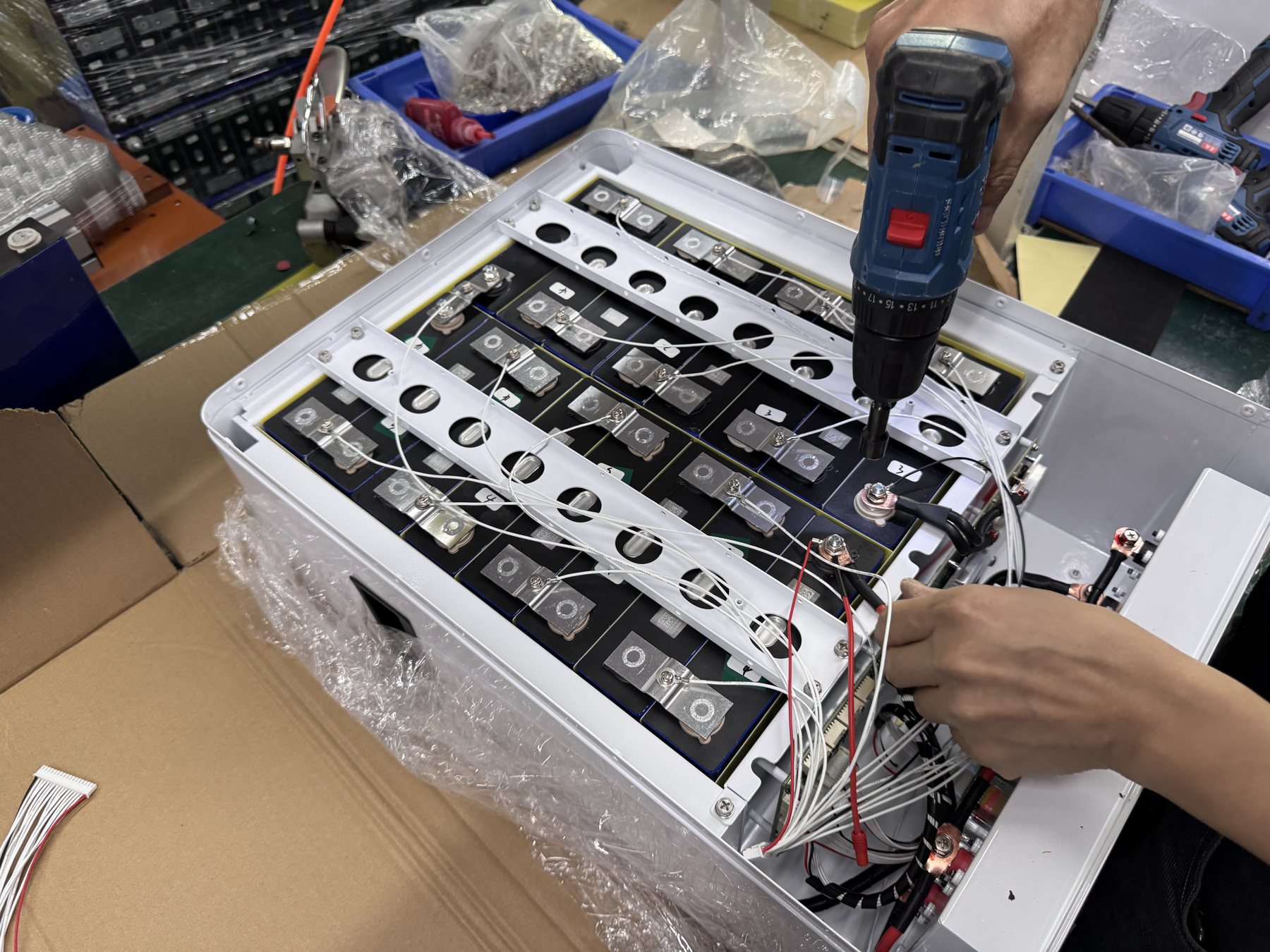
Inspect sample construction for identification, fasteners, insulation, harness routing, connector retention and physical protection. Record each finding with a photograph and disposition. Avoid treating a polished exterior as proof of internal workmanship. Conversely, recognize that an engineering prototype may have temporary features that must be replaced before production-intent validation. The release packet should make that distinction explicit.
Plan endurance and environmental evidence
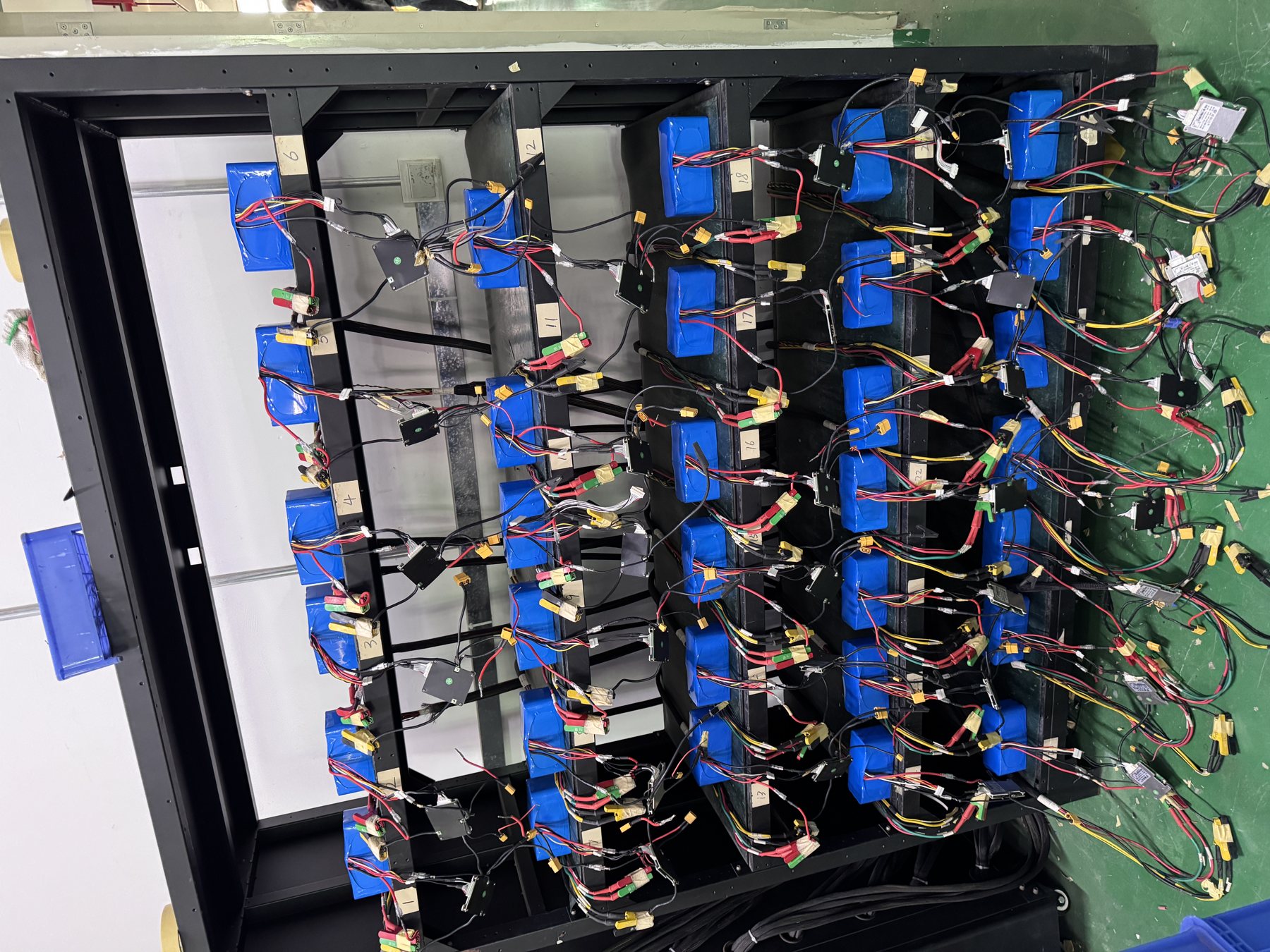
A pilot cannot compress every year of field operation into a few days. It can, however, expose early integration faults through repeated representative cycles. Define a cycle that includes the work segments, rest, charge and restart conditions relevant to the application. Record delivered energy, voltage behavior, temperature, alarms and any operator intervention over repeated runs. Review trends rather than only the final “pass” mark.
For temperature evaluation, separate three questions: whether the pack is permitted to operate at the expected ambient temperature, whether charging is permitted at that temperature, and whether the host can still meet its duty requirement. A chemistry label is not an operating specification. Obtain the exact approved temperature limits and any heating, cooling or derating strategy from the supplier. If the equipment is used outdoors or in cold storage, plan a controlled test at the relevant boundary.
Vibration and shock requirements depend on the machine and transport route. Agree which standards, test profiles or equipment-level trials apply and who is qualified to conduct them. The pack may pass a transport test yet still require a separate mounting validation in the machine. Similarly, a successful machine trial does not replace required transport or market documentation. Keep each evidence type tied to the question it actually answers.
Make quality evidence traceable
Ask how the supplier records cell selection, incoming checks, assembly steps, electrical tests, aging, final inspection and serial-number traceability for the approved model. The buyer does not need every internal record, but should know which records exist, what will accompany each shipment and how a problem can be traced to an affected lot. If the pilot discovers a defect, the corrective action should identify its cause, containment, repair or replacement method, and test evidence for the revised unit.
Define production acceptance separately from engineering validation. Routine checks might cover identification, polarity, open-circuit voltage, insulation, communication, functional response and other model-specific items. Type or design validation may involve deeper testing on selected samples. The parties should agree which checks apply to every pack, which apply by lot, and which require external laboratories. Avoid implying that a report for one configuration automatically covers a changed product.
Documentation must match the actual model, manufacturer and destination. For battery transport, a UN38.3 report or test summary, material safety information and carrier-specific paperwork can serve different purposes. Review the current report number, capacity, applicant, issuing body, date and scope for the exact shipping configuration. YZL POWER's available documents should be requested by model and market; buyers should confirm current acceptance with the carrier and destination before shipment.

Define failure reporting and support before release
The field support process should be part of the pilot, because the quality of evidence collected at a fault determines how quickly a remote team can diagnose it. Prepare a case template with serial number, order reference, equipment and firmware, time of occurrence, recent changes, voltage, current, state of charge, temperature, alarm codes, BMS and host logs, charger settings and photographs of wiring and installation. Train the operator to preserve the first fault state rather than immediately clearing every alarm.
Agree on safety escalation. Smoke, swelling, leakage, unusual odor or uncontrolled heating requires immediate site safety action under the customer's emergency plan, not ordinary troubleshooting by chat. For non-emergency faults, identify who performs first-line checks, who can change settings, and when the battery supplier, equipment OEM or installer must join. Do not return lithium batteries without written handling and transport instructions.
Keep commercial warranty terms in the quotation, purchase documents or contract. A website article cannot define a universal warranty period for every product. The pilot record should identify the approved configuration, intended application and operating limits so the later support team has a clear baseline. A well-documented sample reduces ambiguity when the first field issue appears months later.
A practical stage-gate sequence
Gate 1: requirements complete
The equipment team supplies a load profile, host model and firmware, charger details, installation drawing, environment, expected quantity and destination. The battery team returns a proposed configuration and identifies assumptions. Close missing information before ordering an expensive prototype. If a critical value remains unknown, state the planned measurement and decision owner.
Gate 2: engineering sample ready
Inspect the serial-numbered sample against the approved drawing and revision. Check labels, interfaces, mechanical fit and basic electrical functions before full equipment testing. Record any temporary prototype differences. The sample is released for controlled trials only when the responsible engineers agree it is safe to test under the planned envelope.
Gate 3: integrated performance proven
Run the actual duty cycle, charging pattern and communication state sequence. Capture synchronized battery and host evidence. Track every deviation against a requirement, not merely as a comment in a chat. Corrective changes produce a new revision and a documented retest list. A result is accepted only when the relevant evidence is attached.
Gate 4: production-intent validation
Test units built using the intended materials, harnesses, work instructions and inspection route. Review variation among samples and confirm that manufacturing acceptance limits will detect the important failure modes found during engineering testing. Freeze the released bill of materials and firmware or establish an approved substitution process.
Gate 5: shipment and field readiness
Confirm the exact model's current transport and market documents, packaging, labels, serial-number record, installation instructions, charger settings, service contact and fault evidence template. Make sure the buyer knows which changes require renewed approval. Only then does a pilot become a reliable basis for the volume purchase order.
Questions buyers should ask at the final review
- Which sample serial numbers and configuration revisions produced the accepted results?
- Which equipment, charger and firmware versions were tested, and which variants remain untested?
- What were the measured current peaks, runtime, temperatures and voltage at the host input during the representative cycle?
- Which BMS alarms, limits, shutdown and recovery states were witnessed in the integrated system?
- What changes were made during the pilot, and which tests were repeated afterward?
- What production checks will detect the failure modes found in the sample phase?
- Which model-specific reports and transport documents are current for the destination and carrier?
- Who owns the first response, technical diagnosis and corrective action when the field system fails?
If the answers are scattered among emails, screenshots and verbal assurances, the pilot is not yet a controlled release. Consolidate them into an acceptance report with a requirement matrix, test evidence, open items, approved deviations and signatures. This takes less time than resolving an avoidable problem after many packs have been installed.
Common pilot mistakes
The first mistake is approving a pack by nominal voltage and advertised capacity alone. Neither describes current peaks, charge compatibility, the real energy window or system fault behavior. The second is running only a short demonstration with a fully charged battery. It proves little about a complete shift, low state of charge or repeated charging. The third is changing BMS settings without a revision log; it leaves no reliable record of what the approved sample actually was.
A fourth mistake is treating the supplier's component report as approval of the assembled system in every market. A fifth is using an unrelated certificate, an expired transport appraisal or a report bearing a different model. A sixth is omitting the mechanical installation trial until equipment is already in production. The practical remedy for each is the same: a requirement, an owner, a method of proof and a controlled record.
Finally, do not equate a successful pilot with a promise of zero field failures. The pilot establishes evidence for a defined configuration and operating envelope. Production control, installation, user training and after-sales diagnosis remain essential. Good acceptance language states the tested conditions and the limits of the conclusion.
Next step for an OEM or system integrator
Send the equipment model, duty-cycle description, charger information, installation space and target quantity to the battery engineering team. Include the destination market and the protocol documents if the host uses CAN or RS485. YZL POWER can review the project inputs, propose a model-specific battery configuration and help plan sample validation. For related integration questions, see the product and application overview, the engineering approach and the quality and document review process. If you are still preparing requirements, the 48V system definition guide provides a compact starting checklist.
Project inquiry: Email taokun@xhlmarketing.com or WhatsApp +86 138 0280 9405. Share the approved equipment data and ask for a pilot test matrix, rather than an unsupported universal compatibility claim.